
Specifications
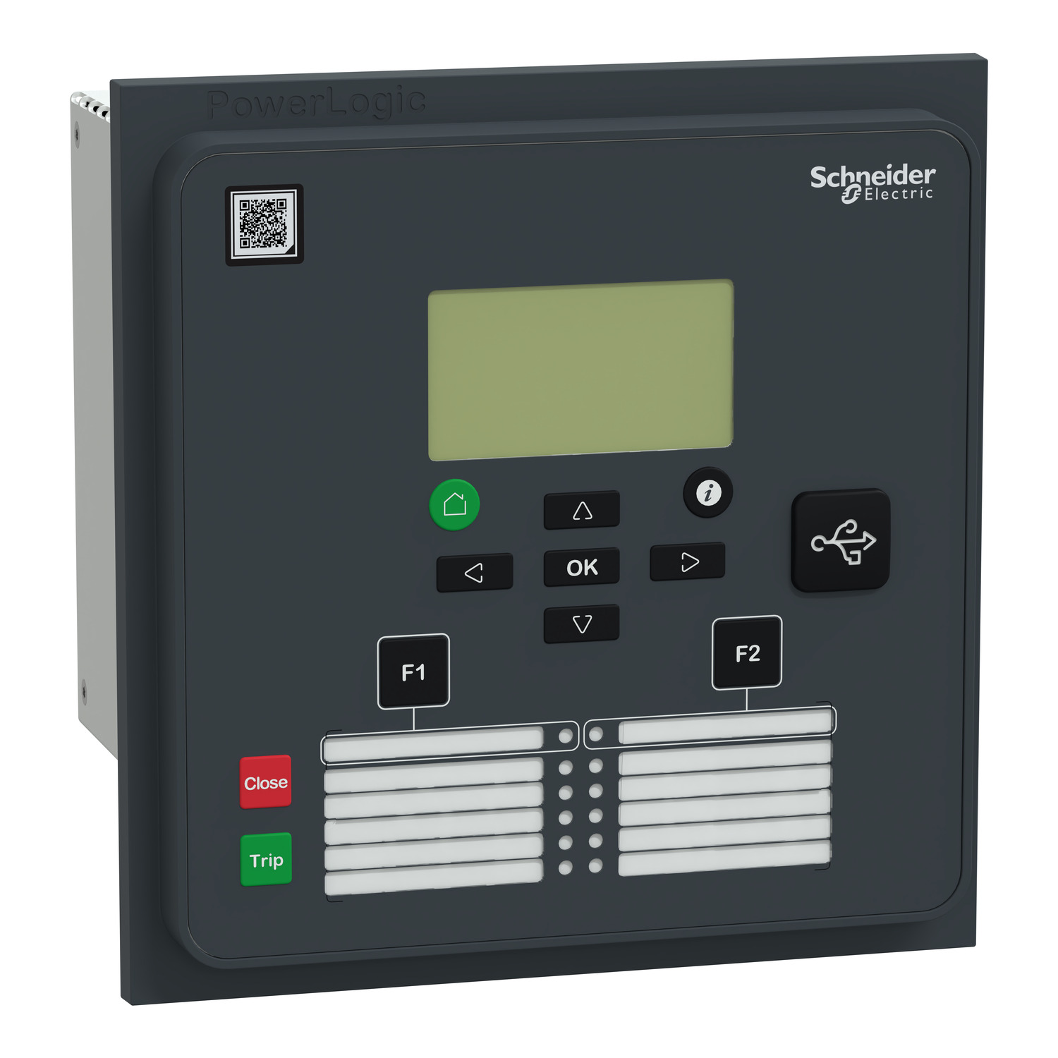
| Range of Product | PowerLogic P3 |
|---|---|
| Product or Component Type | Protection relay |
| Relay application | Universal |
| product reference | P3U30-6AAA1BDAB |
| Mounting case size | 30TE |
| Device mounting | Flush |
| Mounting Mode | Flush mounting |
| power supply | 48…230 V AC/DC |
| measuring inputs | 3 1/5 A CT phase current 1 1/5 A CT residual current 4 100 V/110 V VT voltage |
| number of Digital Inputs (DI) | 16 |
| number of analogue inputs | 0 |
| number of Digital Outputs (DO) | 8 DO 1 watchdog |
| number of analogue outputs | 0 |
| communication ports | Front USB port 1 Rear LC 2 |
| communication protocols | IEC 61850 ed. 1 IEC 61850 ed. 2 IEC 60870-5-101 DNP3 TCP Modbus TCP EtherNet/IP |
| Redundancy communication port protocol | RSTP PRP |
| Cybersecurity | Password protection Port hardening |
| protection functions | Phase overcurrent 50/51 Directional phase overcurrent 67 Earth fault overcurrent 50N/51N Directional earth fault 67N Transient earth fault 67NI Capacitor bank unbalance 51C Broken conductor 46 I2/I1 Cold load pick-up H2 detection 68H2 H5 detection 68H5 Cold load pick-up 68H5 Breaker failure 50BF Switch ON to fault (SOTF) Directional active underpower 37P Fault locator 21FL Recloser 79 Phase undercurrent 37 Excessive starting time, locked rotor 48/51LR Motor restart inhibition 66 Switch ON to fault (SOTF) 81R Capacitor overvoltage 59C Negative sequence overcurrent 46 Overvoltage 59 Undervoltage 27 Positive sequence undervoltage 27P Earth fault overvoltage 59N Underfrequency 81/81N Rate of change of frequency 81R Synchro-check 25 Lockout relay 86 CT supervision 60 VT supervision 60 Capacitor overvoltage 59C 8 Programmable stages 99 8 Programmable curve Programmable curve 60 |
| Arc flash protection | No |
| measurement functions | Current 3-phase Current zero sequence Current positive sequence Current negative sequence Current ratio of negative and positive Voltage phase to earth Voltage phase to phase Voltage zero sequence Voltage positive sequence Voltage negative sequence Voltage ratio of negative and positive Short circuit fault reactance Fault location current Earth fault reactance Frequency Earth fault reactance positive sequence Active power Reactive power RMS reactive power Apparent power Frequency ratio of negative and positive RMS apparent power Active energy Reactive energy Active power phase to phase Cos φ Tan φ Power angle Power factor Current phasor diagram view Current 2nd, 15th harmonics with THD Voltage 2nd, 15th harmonics with THD Condition monitoring CB wear Voltage interruption Apparent power zero sequence RMS apparent power phase to earth Active energy zero sequence Reactive energy ratio of negative and positive Condition monitoring CB wear phasor diagram view Voltage interruption 2nd, 15th harmonics with THD |
| control functions | Switchgear control and monitoring Programmable switchgear interlocking Local control on single-line diagram Local control with I/O keys Local/remote control 2 function keys Mobile application with Easergy SmartApp Web-server Programmable logic |
| controllable switchgear devices | 4 controlled + 8 displayed |
| number of setting groups | 4 |
| monitoring functions | Trip circuit supervision 74 Circuit breaker monitoring Relay self-monitoring |
| logs and records | Event recording Disturbance recording Tripping context |
| Switchgear diagnosis type | CT supervision TCS Trip circuit supervision TCS |
| Connections – terminals | Screw removable (digital input/output) Pin removable (voltage transformer) Pin removable (current transformer) |
| Operating threshold | 24 V AC/DC |
|---|---|
| Time synchronisation protocol | SNTP |
| Software name | ESetup Easergy Pro virtual simulation test Easergy SmartApp |
| Web server | Embedded HTTP server |
| Display type | LCD 128 x 64 pixels with single line diagram |
| Number of key | 2 customizable |
| Local signalling | 4 LEDs 8 LEDs programmable |
| Height | 6.7 in (169.5 mm) |
| Width | 6.7 in (170 mm) |
| Depth | 8.07 in (205 mm) |
| Net weight | 5.5 lb(US) (2.5 kg) maximum |
Reviews
There are no reviews yet.